There is a wide variety in the production process of different wood products. These highly engineered timber products are known as “Engineered Wood Products” (EWP). In this section the production processes of the three most important EWPs for the timber construction sector are explained. We start with Plywood, move on to Glulam and finish with Cross Laminated Timber (CLT).
1. Plywood
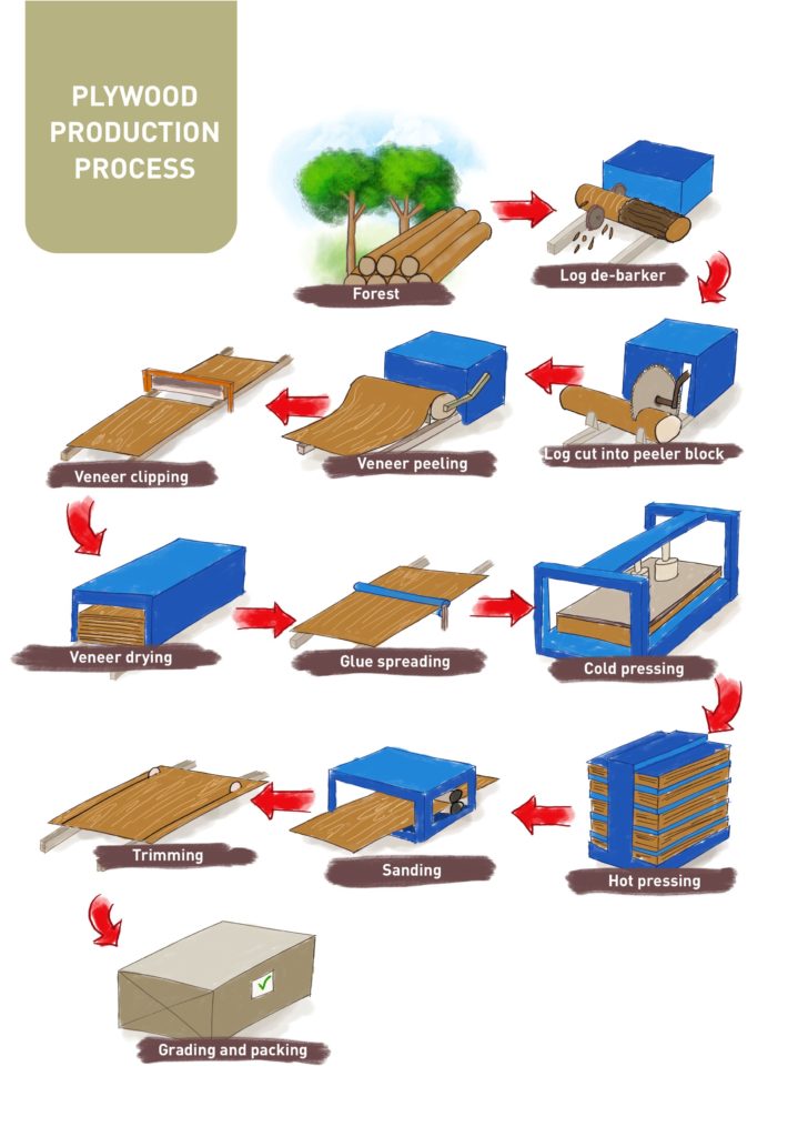
After the harvesting the roundwood logs are transported to the production site, where the bark is removed from each log. This step is called debarking.
The logs are cut into defined lengths of 2,60m (face and back veneer) and 1,30m by circular saw. These log sections are now processed into continuous veneer strips using a Rotary Machine. The standard thickness of each veneer sheet used in the core of the plywood panel range from 1.2mm to 3.6mm in thickness, whereas the thickness from the face veneer sheets range from 0.5 to 1,0mm.
The continuous veneer is then cut into defined lengths, stacked and dried to a wood moisture content between 12% for core veneer and 14% for face veneer.
The dried veneer strips are selected and defects are cut out. The standard sizes for veneer stripes are 4×4 ft , 4×8 ft , 3×6 ft and 3x7ft. Some producers scaff-joint (create a larger bonding area) veneer strips to transform 4×4 ft (1,2mx 1,2m) veneers (shortcore) to 4×8 ft (1.2m x 2.4m) veneers (longcore). The adhesives used are urea formaldehyde (UF), melamine formaldehyde (MF), melamine urea formaldehyde (MUF) or phenolic resin. More modern technologies can join individual veneers using finger joints.
Depending on the customer’s requirements, individual veneer strips can be sorted according to their application and quality, roughly distinguishing between face, back, shortcore, and longcore veneer.
To finally produce a plywood panel, glue (MF, UF or PUR = Polyurethane resin) is applied to the individual veneer strips by means of glue spreader. The glue-coated veneers are stacked in thicknesses between 2.7mm and 25mm and pushed into a cold press for pre-pressing. This is an important process as it significantly affects the quality of the glue bonding, the surface treatment with glue and the pressing time. After cold pressing, the plywood panels are moved into a hot press. The most common size for plywood sheets used in building construction are 1.2m wide by 2.4m long.
After the plywood has cooled, the plywood is sanded to achieve the desired surface finish. As a final step, the plywood sheets are cut to the final size according to the customer’s request and standard requirements, inspected once more and packed for transportation.
2. Glued Laminated Timber (GLT)
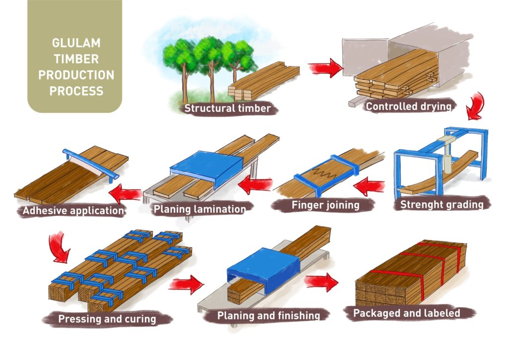
As the first step in the production of Glulam beams, the sawn timber has to be dried in a kiln to a moisture between 12-15%.
After drying, the lumber has to be sorted and graded on different characteristic features, depending on the final strength needed in the beam. Big knots and other timber faults have to be cut out so that they do not negatively influence the strength of the final product. This classification is an important step to standardise the final product and give the engineers characteristic values of the material as a basis for static calculation.
In the next step, the short pieces of sawn timber are glued together in length with finger joints to get one long piece, which should be as long as the final beam is going to be. As adhesive for the finger joints a PUR or MF glue should be used. The parts have to be pressed together under high pressure to have a good quality joint.
After drying the adhesive, the pieces need to be planed to have a smooth surface and proper right-angles. These lamellas can now be glued together in height, depending on the customer’s requirements. For glueing the lamellas together in height, a MF or PUR adhesive which is very resistant should be used as well. After glueing the lamellas together, the whole beam has to be planed again to the final section and to have a nice surface.
In the glulam production, the possibilities of shape and size of the beams are almost unlimited. Of course it depends on the maximum size of the press, the planer and of the transport. The technology of finger joints makes it possible to use small pieces of timber to make bigger beams and increase the value of these timber.
3. Cross Laminated Timber (CLT)
Cross Laminated Timber (CLT) is a plate-like engineered timber product, which usually consists of an odd number of layers (3,5,7 or more) which are staked orthogonally to each other, and bonded with structural adhesives or less commonly mechanically with nails or dowels.
CLT has become of global interest due to its numerous advantages over mineral-based solid construction materials. The scope of application for CLT lies mainly in load-bearing, non-load-bearing and reinforcing components (wall-roof-and ceiling elements).
By the crosswise arrangement of the longitudinal and transverse lamellae, the swelling and shrinkage in the plate plane is reduced to an insignificant minimum, but the static loadability and dimensional stability are considerably increased.

Figure: Cross Laminated Timber (ProHolz Austria, 2017)
For the CLT-production in Europe mainly softwood species such as White fir (Abies alba), Norway spruce (Picea abies), Scots pine (Pinus sylvestris), European Larch (Larix decidua), Douglas fir (Pseudotsuga menziesii) and even Swiss Pine (Pinus cembra), for high appearances, are used. With nowadays technique plate dimensions of 3 m in width (4,8 m possible), 16,5 m in length (30 m possible) and 400 mm in thickness (500 mm possible) are most common.
The single steps behind the CLT-Production
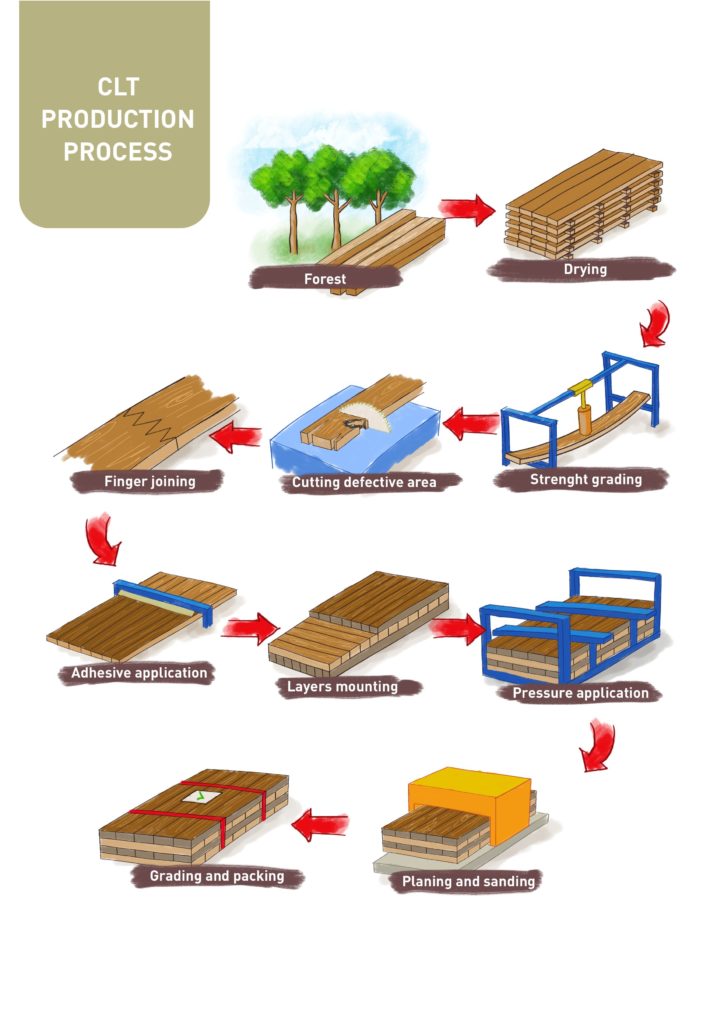
After harvesting roundwood logs, a sawmill transforms the timber into sawn lamellas, which range from 80 – 240 mm in width and 10 -35 mm in thickness. The ratio width to thickness should be 4 : 1. The key to a successful CLT manufacturing process is consistency in the lumber quality and strict controls of the parameters that impact the quality of the adhesive bond.
After the de-stacking process, the moisture content of each lamella is measured and lamellas which do not meet the required specifications are sorted out of the production flow.
Next, the material is visually or mechanically graded to strength classes. It is very important to ensure that all boards within a single layer are of the same grade. Normally CLT is composed of layers of equal strength properties, but a combined, symmetric composition of layers with different strength classes is also possible. Currently the product CLT is primary composed of C24 (S10) according to EN 338 for a homogenous layup.
Based on the output of strength grading, local growth characteristics, which do not meet the requirements of the strength class, are cut out. Now the lamellas are of random length and the board segments must be reconnected to the desired length for parallel and longitudinal CLT layers by means of finger joints, aiming to still remain the main part of the original board.
Currently, melamine-urea-formaldehyde (MUF) and one-component polyurethane adhesives (1K-PUR) as well as emulsion polymer isocyanate adhesives (EPI) are used for finger jointing.
After finger jointing, the lamellas are planed for further processing. After planing, the lamellas need to be divided in longitudinal and transversal lamellas. The longitudinal lamellas go straight to the layering station, whereas the transversal lamellas need to be cut into the desired length. After cutting the transversal lamellas, they are turned in an ankle of 90° to further proceed through the production line. Now the transversal and longitudinal lamellas are ready for the stacking process
The CLT layer forming depends on the capacity and design of the production line. In Europe the most common layering systems are band conveyors or vacuum lifting devices. In plants with low capacity CLT layups can also be done by human operators.
The application of the adhesive to surface bonding is in general carried out mechanically and contactless. In general there are four press systems available for CLT manufacturing:
- Hydraulic Press (0,1 – 1,5 N/mm2),
- Pneumatic Press (0,1 – 1,0 N/mm2),
- Screws, Brackets or Nails (0,1- 0,2 N/mm2) or
- Vacuum Press (0,05 – 0,1N/mm2).
After pressing the CLT panel, a short buffer is included to cure the glue. During the face bonding, adhesive resigns and occurs on the edges of the CLT element. Therefore panels get a finish by trimming the edges.
An infeeding- machine carries the CLT element after pressing and trimming the edges into a planing or sanding machine, where the surface on both sides of the element is treated.
Common devices for cutting CLT elements are portal machines operating as multiple processing centers, which accomplish all relevant processes such as trimming, cutting, milling, drilling on both side faces and all four narrow faces, including marking and labelling of the element.
Last production step is the packaging and shipping of the customized CLT panels. The CLT elements are usually bundled together and strapped vertically or horizontally on a truck for further transportation.